Products
HFD Series
1.25kV MCP + 4kV Scintillator PSU Floating At Up To 10kV
5kV, RD7.5kV, RD010kV, RD012kV
Application: MCP + SCINT Detectors for Mass Spectrometers & Electron Microscopes
- 2.5kV, 5kV, 10kV isolation
- Remote, Ground Referenced voltage programming
- 24V Ground Referenced Supply
- High Stability MCP, (temp-co <200ppm)
- MCP Voltage monitor
- Flashover & short circuit protected
- Scint voltage clamped to protect the Scintillator
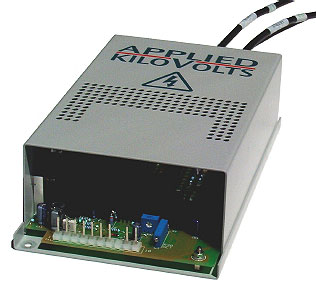
These power supplies, based on the standard HF series (data sheet HF Series refers) are intended to power detectors where a Microchannel Plate is directly coupled to a Scintillator to make a composite detector. The one unit provides the HV for both sections of the detector, and can be floated on voltages up to ±10 kV. These units use differential feedback techniques to allow the 24 volt power, control and monitor signals to be at ground potential.
The control input sets the MCP voltage up to 1.25kV, while the Scint voltage follows the MCP voltage, but is clamped at approximately 4.75kV above the MCP voltage. This output clamp also helps protect the Scintillator in the event of arcing.
| Electrical Specification | |||||||
|---|---|---|---|---|---|---|---|
| Unit Type | MCP Output | Scintillator Output | Isolation | Output Ripple | Inhected Ripple | Size (mm) | Weight (kg) |
| HFD005PAA2.5 | 112V to 1.25kV At 100μA |
MCP Volts x4.5 Clamped @ 4.75kV |
±2.5kV | MCP <150mV pk to pk SCINT <500mV pk to pk |
<50mV (pk-pk) | 185 x 120 x 60 | 1.5 |
| HFD005PAA005 | 112V to 1.25kV At 100μA |
MCP Volts x4.5 Clamped @ 4.75kV |
±5kV | MCP <150mV pk to pk SCINT <500mV pk to pk |
<50mV (pk-pk) | 185 x 120 x 60 | 1.5 |
| HFD005PAA010 | 112V to 1.25kV At 100μA |
MCP Volts x4.5 Clamped @ 4.75kV |
±10kV | MCP <150mV pk to pk SCINT <500mV pk to pk |
<50mV (pk-pk) | 185 x 120 x 60 | 1.5 |
| 1) ripple injected into the power supply providing the floating voltage, measured assuming load capacitance of 1000 pF. | |||||||
The critical MCP voltage, for setting the gain of the detector, is directly controlled by the 10V control input. The Scintillator voltage is X4 the MCP volts, on top of the MCP voltage, so with an MCP voltage of 1kV the Scintillator will be at 4kV (i.e. 4kV above the MCP voltage.) We manufacture a large number of these supplies, customised for different detector characteristics. The ratio of MCP voltage to Scintillator Voltage, and final Scintillator clamping voltage and Zout can readily be customised for your specific detector application. Please consult the factory with your details.
| Input | +24V dc ±10% <0.7A. 0V input common to chassis. |
|---|---|
| Control of MCP Output At Ground Potential |
|
| MCP Voltage Monitor | 0V to +10V ±3% for 0% to 100%. (Zout= 10k) |
| MCP Temp Co-efficient | <0.02% / ºC |
| MCP Drift (after 1 hour warm up) | <0.1% per hour |
| SCINT o/p Voltage | MCP X4.5 ±5% clamped at 4.75kV ±15% Clamp Temp co <650ppm/°C |
| Line Regulation | <0.2% for 1V change in input voltage |
| Load Regulation | <0.2% for 25% to 100% MCP voltage Note Scintillator o/p has Zout of 100Mohms |
| Protection (all outputs) | Protected against intermittent arcing and continued short circuit to ground |
| Environmental Specification | |||
|---|---|---|---|
| Temperature, Storage | +10°C to +50°C. | Humidity (RH) <31°C | 80% maximum |
| Temperature, Operating | -35°C to +85°C. | Humidity (RH) >30°C | Decrease linearly to 50°C |
| Altitude, Operating | Up to 2,000m. | Altitude, storage | Up to 18,000m |
| Mechanical Specification | |
|---|---|
| Mountings | 3 off M4 clearance holes—see outline drg |
| Input & Control | Molex 0.2” 12 way connector (24V power, control and monitor are all at Ground potential.) |
| Outputs | By three 0.5m flying screened (shielded) leads type URM43 labelled ‘INPUT’, ‘MCP’, ‘SCINT’ |

 Website